NT3200-32-MX Cashless Vending Machine — Technical Manual
Model: NT3200-32-MX Document version: v26.5.1 Manufacturer: maxcrc GmbH
1. Introduction
Section titled “1. Introduction”The NT3200-32-MX Cashless Vending Machine is a self-service control and payment unit designed for managing laundry equipment and enabling seamless cashless transactions.
The device is intended for use in unattended or semi-attended environments such as laundromats, residential laundry rooms, and commercial washing facilities. It provides users with an intuitive interface to select services, initiate washing or drying cycles, and complete payments using modern cashless technologies.
The NT3200-32-MX integrates multiple hardware components into a single unit:
- A touchscreen display for user interaction and service selection
- A built-in receipt printer for transaction confirmation
- A combined QR code and RFID reader for user identification, gift card acceptance and validation
- A contactless payment terminal supporting bank cards and mobile payments
The system operates entirely without cash handling. All payments are processed via cashless methods, improving reliability, security, and operational efficiency.
This technical manual provides detailed information for installation, configuration, integration, and maintenance of the NT3200-32-MX unit within the Treysee vending ecosystem.
2. Safety and Usage
Section titled “2. Safety and Usage”This section provides important safety instructions and usage guidelines for the NT3200-32-MX Cashless Vending Machine. Following these recommendations ensures safe operation, prevents equipment damage, and prolongs device lifespan.
2.1 General Safety Instructions
Section titled “2.1 General Safety Instructions”- The device must be installed and operated only by qualified personnel.
- Always disconnect the power supply before performing any maintenance or service operations.
- Do not open the enclosure while the device is powered on.
- Ensure that the device is properly grounded.
- Do not use the device if visible damage to the housing, cables, or components is detected.
- Keep the device away from water, excessive humidity, and direct heat sources.
2.2 Electrical Safety
Section titled “2.2 Electrical Safety”- Use only the specified power supply and voltage parameters.
- Avoid overloading electrical circuits.
- Ensure stable power conditions; use surge protection if necessary.
- Do not operate the device with damaged power cables.
2.3 Operational Safety
Section titled “2.3 Operational Safety”- The device is designed for indoor use only.
- Do not block ventilation openings.
- Avoid exposure to dust, liquids, or aggressive chemicals.
- Do not place heavy objects on the device.
2.4 Usage Guidelines
Section titled “2.4 Usage Guidelines”- The NT3200-32-MX supports cashless payments only. No cash handling is available.
- Users interact with the system via the touchscreen interface.
- Identification and access may be performed using:
- QR codes
- RFID cards
- Payments are processed via a contactless payment terminal (bank cards or mobile wallets).
2.5 Maintenance and Service
Section titled “2.5 Maintenance and Service”- Regularly inspect the device for dust accumulation and clean it using dry, soft materials.
- Do not use liquid cleaners directly on the device.
- Service operations must be performed only by authorized personnel.
- Replace paper in the receipt printer according to manufacturer recommendations.
2.6 Misuse Prevention
Section titled “2.6 Misuse Prevention”- Do not attempt to modify or bypass system components.
- Do not use unauthorized peripherals or accessories.
- Any misuse may result in system malfunction and void warranty.
2.7 Emergency Situations
Section titled “2.7 Emergency Situations”In case of malfunction:
- Disconnect the device from power immediately.
- Do not attempt self-repair unless qualified.
- Contact technical support.
Proper adherence to these safety and usage guidelines ensures reliable and secure operation of the NT3200-32-MX device.
3. Product Description
Section titled “3. Product Description”The NT3200-32-MX manages cashless payments and provides access control for laundry facility services, including:
- Washing and drying program selection and start
- Liquid and powder detergent dispensing
- QR-code and RFID gift card acceptance and validation
- Discount management
3.1 Components
Section titled “3.1 Components”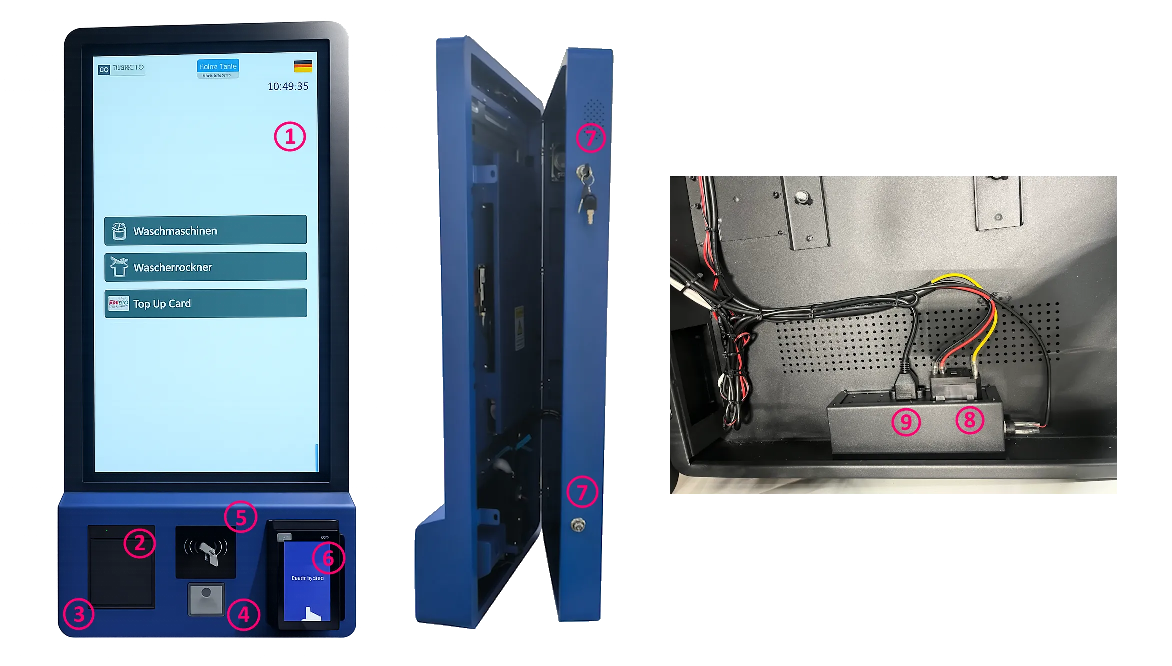
The device integrates the following components:
| No. | Component | Description |
|---|---|---|
| 1 | 32″ Capacitive Touch Display** | Main user interface, portrait orientation |
| 2 | Thermal Printer (80 mm)** | Silent receipt, ticket, and discount printing |
| 3 | Printer Lid Button** | Opens the printer compartment for paper replacement |
| 4 | QR-Code Reader** | Built-in scanner for QR codes and barcodes |
| 5 | RFID Reader / Writer** | Reads and writes RFID gift cards and service tokens |
| 6 | Card Terminal** | Contactless payment — IM30 or compatible |
| 7 | Side Opening Locks** | Secure access to internal components (2 locks) |
| 8 | Power Connector** | 220 V AC inlet |
| 9 | LAN Connector** | Ethernet network connection |
3.2 Power Consumption
Section titled “3.2 Power Consumption”| Parameter | Value |
|---|---|
| Supply voltage | 220 V AC |
| Frequency | 50–60 Hz |
| Phase configuration | 1 / N / PE |
| Maximum power draw | 150 W |
3.3 Standards & Certifications
Section titled “3.3 Standards & Certifications”The NT3200-32-MX complies with the following standards:
- CE — European Conformity
- FCC — Federal Communications Commission (USA)
- RoHS — Restriction of Hazardous Substances
⚠️ WARNING
Incorrect installation may result in electric shock, fire, or equipment damage. This manual must be read in full before beginning installation. All electrical work must be performed by a qualified technician in accordance with local regulations.
3.4 Dimensions & Mounting Pattern
Section titled “3.4 Dimensions & Mounting Pattern”All dimensions are in millimetres. Refer to the drawing below.
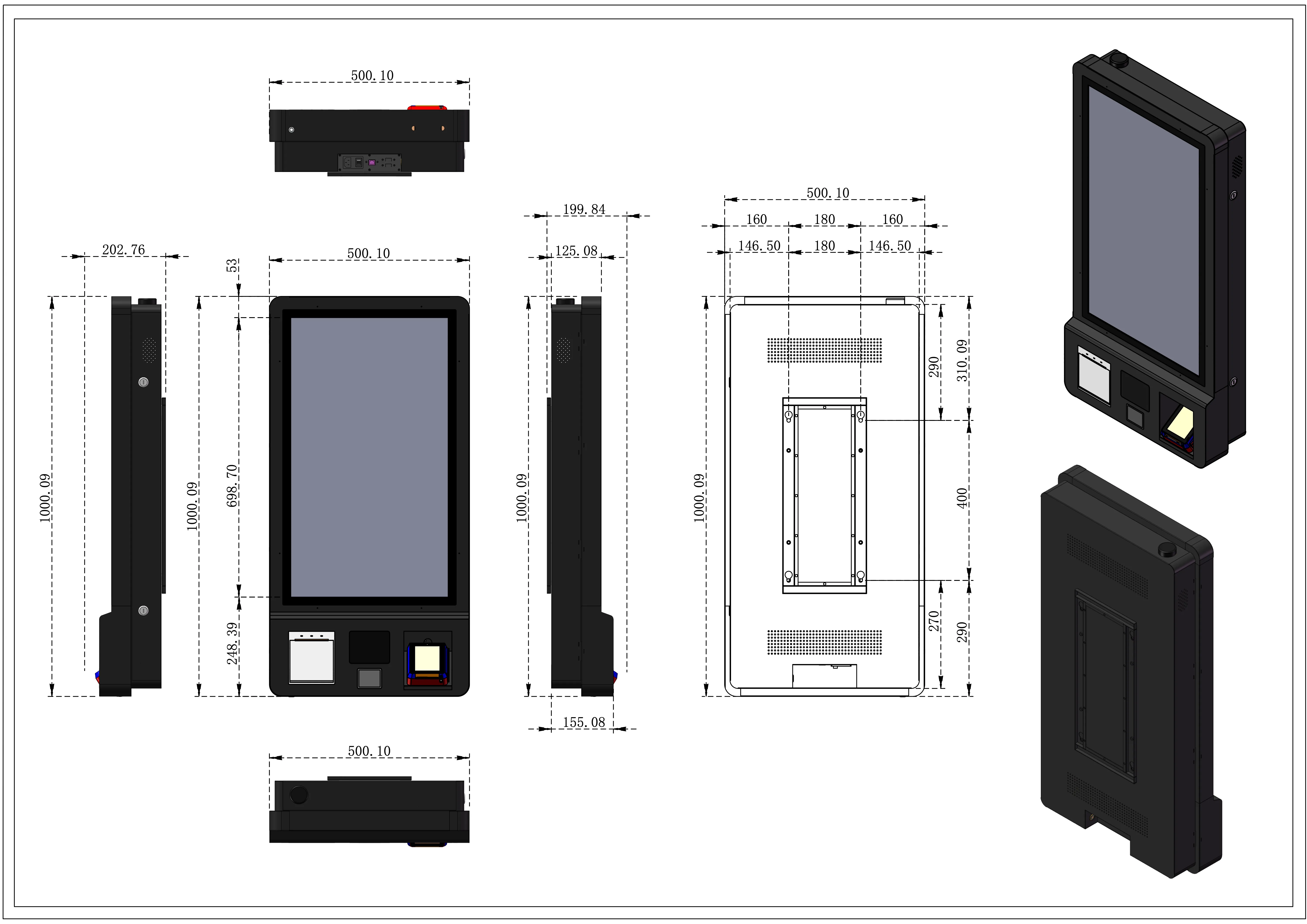
| Measurement | Value (mm) |
|---|---|
| Overall height | 1000.09 |
| Overall width | 500.10 |
| Overall depth (front + bracket) | 202.76 |
| Depth at thinnest point (side) | 125.08 |
| Screen area height | 698.70 |
| Lower module height | 248.39 |
| Mounting plate width | 199.84 |
| Mounting plate depth | 155.08 |
| Mounting hole span — horizontal (outer) | 500.10 |
| Mounting hole span — horizontal (inner) | 180 |
| Mounting hole margin — left/right | 160 / 146.50 |
| Mounting hole span — vertical (outer) | 310.09 |
| Mounting hole span — vertical (inner) | 400 |
| Mounting hole margin — bottom group | 270 / 290 |
| Enclosure front panel depth | 53 |
📐 see Picture 2 for the complete multi-view engineering drawing including front, rear, side, top, and bottom views with full VESA/wall-mount hole positions.
4. Installation
Section titled “4. Installation”⚠️ Before starting: Ensure that mains power to the installation area is switched off at the breaker. Verify the wall structure can support a minimum load of 40 kg (device weight + safety margin).
4.1 Preparation Checklist
Section titled “4.1 Preparation Checklist”Before mounting the device, prepare and route the following cables to the installation point from behind the wall:
- 230 V AC power cable (3-wire: L / N / PE) with appropriate cross-section for 150 W load
- LAN cable (Cat5e or better, shielded recommended)
- IO Board connection line — 4-wire cable connecting to the IO Board installed on the back side of the wall; this board interfaces with the washing machines, dryers, and detergent dispensers
4.2 Mounting Steps
Section titled “4.2 Mounting Steps”-
Mark the wall anchor points using the rear mounting template from the dimensional drawing.
Key horizontal spacing: 180 mm (inner) / 500.10 mm (outer between bracket edges).
Key vertical spacing: 400 mm (inner hole span). -
Drill anchor holes at the marked positions. Use appropriate wall plugs for the wall material (concrete, brick, or drywall with backing plate).
-
Install the wall bracket — torque all fasteners to the specification of the anchor system used.
-
Route cables through the wall opening behind the bracket so they are accessible once the device is hung.
-
Hang the device onto the wall bracket. Two people are required — the unit weighs 20–25 kg.
-
Verify that both side locks are in the open position before connecting cables inside the enclosure.
-
Connect cables:
- Power cable → Power Connector (rear bottom)
- LAN cable → LAN Connector (rear)
- IO Board cable → IO Board header (internal, 4-pin)
-
Close and lock both side locks with the supplied keys.
-
Restore mains power and proceed to first-start verification.
4.3 Junction Box
Section titled “4.3 Junction Box”The Junction Box is a surface-mounted protective enclosure designed to house the IO Board used for dryer machine control. The box provides IP65 protection against dust and moisture, making it suitable for installation in demanding service environments.
4.3.1 Purpose
Section titled “4.3.1 Purpose”The Junction Box is used to install the IO Board that controls 1 to 12 dryer machines, depending on the IO Board type and channel configuration.
4.3.2 Physical Data
Section titled “4.3.2 Physical Data”| Parameter | Value |
|---|---|
| Colour | White |
| Installation type | Surface-mounted |
| Protection class | IP65 |
| Dimensions (D × W × H) | 7 cm × 11 cm × 15 cm |
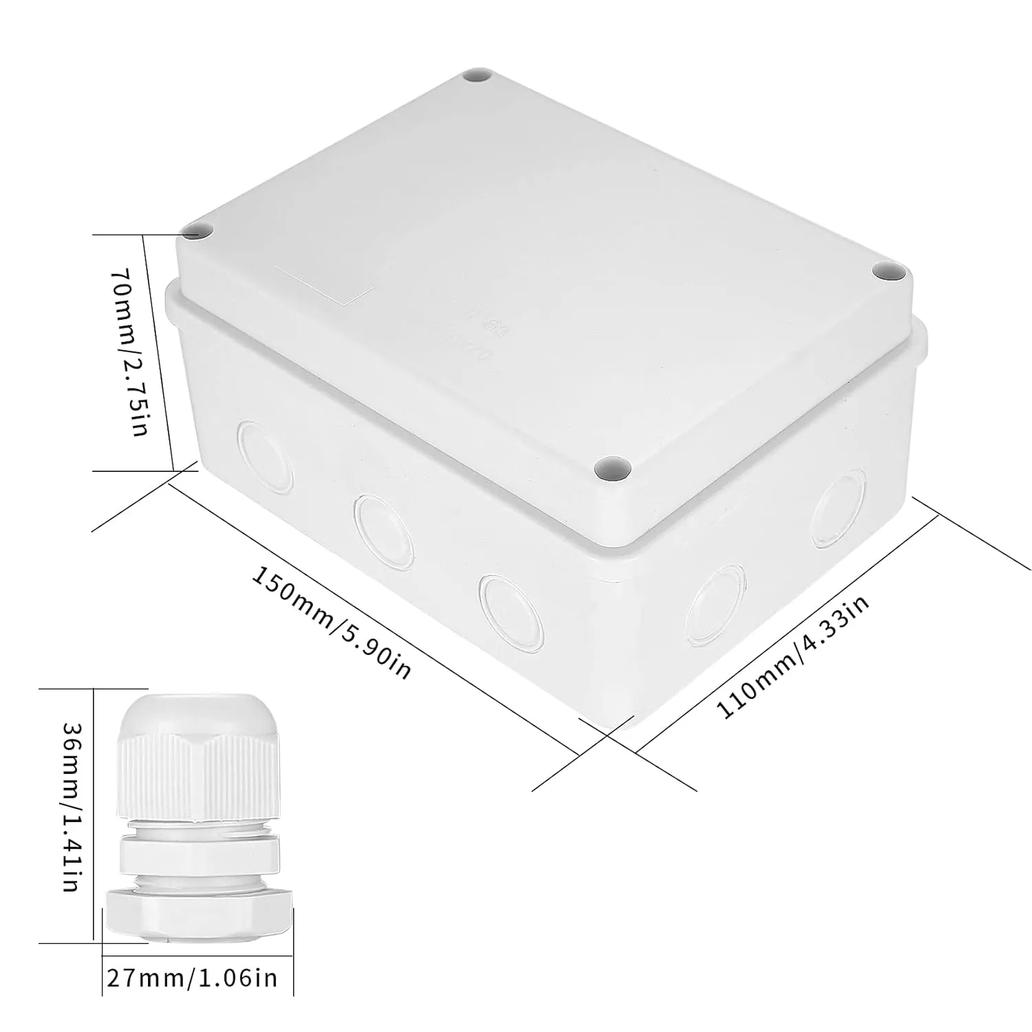
- Mount the IO Board inside the Junction Box before final wall installation.
- Keep cable entries sealed to preserve the IP65 rating.
- Use the Junction Box when the IO Board is deployed for dryer machine control in wet or dusty areas.
4.3.3 Wiring Diagram
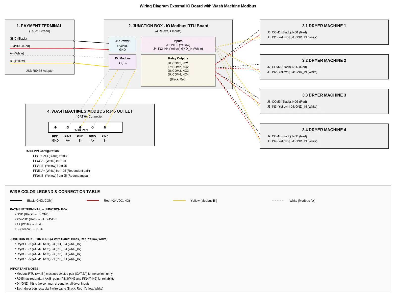
Section titled “4.3.3 Wiring Diagram”The diagram illustrates the connection of the cashless vending unit to the Modbus IO board and multiple dryers, including power supply, communication lines, and relay control signals.
4.3.4 Vending Machine, IO Board, and Dryers
Section titled “4.3.4 Vending Machine, IO Board, and Dryers”The Vending Unit (VU) provides power and RS485 communication to the IO Board. The IO Board then distributes relay start signals and feedback inputs to one to four dryer machines.
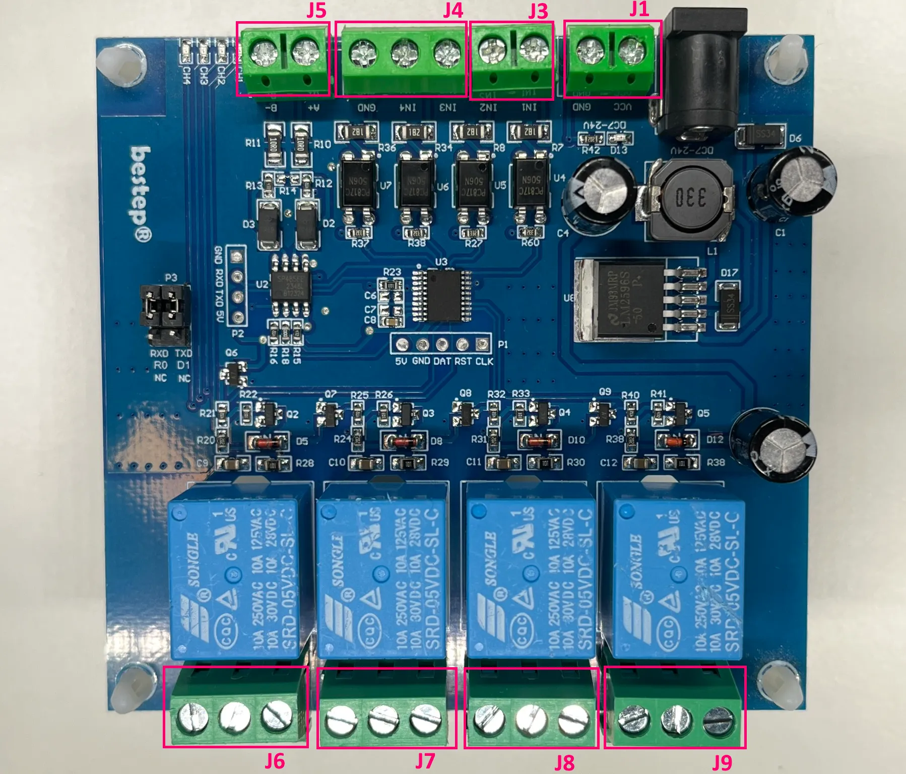
VU to IO Board
Section titled “VU to IO Board”| VU Wire | Color | IO Board Terminal | Signal |
|---|---|---|---|
| +12/24 VDC | Red | J1 | Power supply |
| GND | Black | J1 | Power ground |
| RS485 A+ | Yellow | J5 | RS485 A+ |
| RS485 B- | White | J5 | RS485 B- |
IO Board to Dryer 1
Section titled “IO Board to Dryer 1”| IO Board Terminal | Wire Color | Dryer Connection | Signal |
|---|---|---|---|
| J6 / NO1 | Red | Start input | Relay start pulse |
| J6 / COM1 | Black | Common | Relay common |
| J3 / IN1 | Yellow | Busy feedback | Dryer busy signal |
| J4 / GND_IN | White | Feedback ground | Feedback reference |
IO Board to Dryer 2
Section titled “IO Board to Dryer 2”| IO Board Terminal | Wire Color | Dryer Connection | Signal |
|---|---|---|---|
| J7 / NO2 | Red | Start input | Relay start pulse |
| J7 / COM2 | Black | Common | Relay common |
| J3 / IN2 | Yellow | Busy feedback | Dryer busy signal |
| J4 / GND_IN | White | Feedback ground | Feedback reference |
IO Board to Dryer 3
Section titled “IO Board to Dryer 3”| IO Board Terminal | Wire Color | Dryer Connection | Signal |
|---|---|---|---|
| J8 / NO3 | Red | Start input | Relay start pulse |
| J8 / COM3 | Black | Common | Relay common |
| J4 / IN3 | Yellow | Busy feedback | Dryer busy signal |
| J4 / GND_IN | White | Feedback ground | Feedback reference |
IO Board to Dryer 4
Section titled “IO Board to Dryer 4”| IO Board Terminal | Wire Color | Dryer Connection | Signal |
|---|---|---|---|
| J9 / NO4 | Red | Start input | Relay start pulse |
| J9 / COM4 | Black | Common | Relay common |
| J4 / IN4 | Yellow | Busy feedback | Dryer busy signal |
| J4 / GND_IN | White | Feedback ground | Feedback reference |
- Red and black wires carry the start pulse from the relay.
- Yellow and white wires carry the busy feedback from the dryer.
- The “busy” signal from the Dryer is a positive voltage pulse ranging from +12 VDC to +24 VDC between GND_IN and the corresponding IN1–IN4.
- One IO Board supports up to four dryer machines when wired according to the available relay and input channels.
- Keep cable runs short.
4.3.5 Wash Machines RS485 Bus
Section titled “4.3.5 Wash Machines RS485 Bus”The Wash Machines RS485 Bus connects the Vending Machine to the washing machines through an external RS485 adapter and RJ45 cabling.
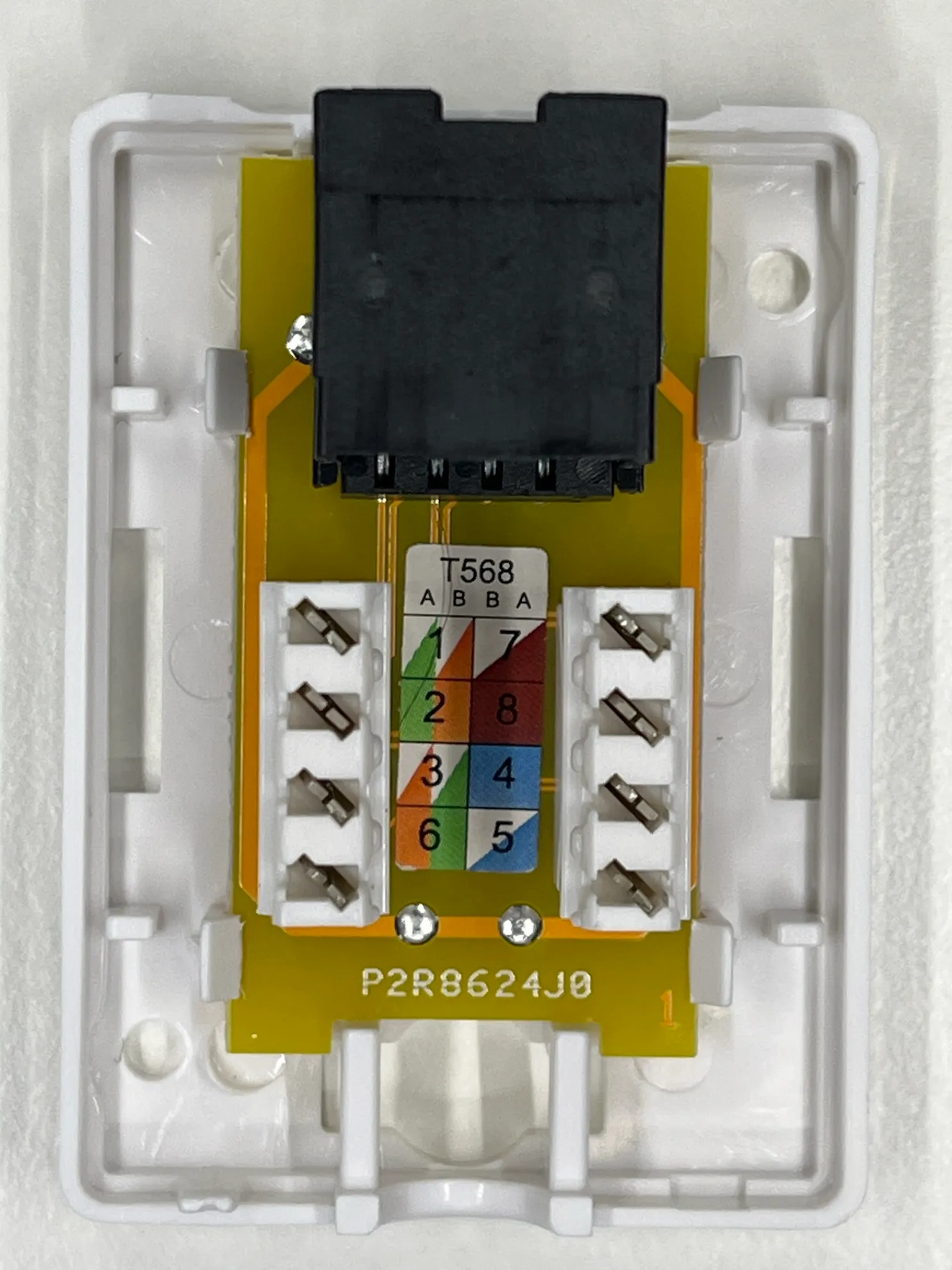
Laundry Machine Connection Socket (RJ45 / Modbus)
Section titled “Laundry Machine Connection Socket (RJ45 / Modbus)”This socket is a communication interface used to connect washing machines and dryers to the central control system (Vending Unit) via Modbus RTU using an RJ45 connector.
The socket is based on a standard module with terminal blocks and T568A/B color coding, simplifying connection of twisted pair cables (CAT5/CAT6).
Key Features
Section titled “Key Features”- Connection type: RJ45 (8P8C)
- Interface: RS485 (Modbus RTU)
- Wiring standards supported: T568A / T568B
- Wire termination: spring terminals (tool-less or tool-assisted)
- Purpose: data communication and control signal transmission between vending unit and machines
Pin Assignment
Section titled “Pin Assignment”- PIN1 GND - ground (Black) from J1
- PIN3 - A+ (White) from J5
- PIN4 - B- (Yellow) from J5
- PIN5 - A+ (White) from J5 (Redundant pair)
- PIN6 - B- (Yellow) from J5 (Redundant pair)
Application
Section titled “Application”Used for connecting:
- washing machines
- dryers
- detergent dispensing systems
to the central vending/control unit
Connection Order
Section titled “Connection Order”- Vending Machine → USB-RS485-WE Adapter
- USB-RS485-WE Adapter → RJ45 outlet
- RJ45 outlet → flat CAT5 patch cable
- Cable length: 2 to 5 meters
- Flat CAT5 patch cable → RJ45 Y-connector of the first washing machine
- First washing machine Y-connector → next washing machine Y-connector
- Continue the chain from one RJ45 Y-connector to the next until all washing machines are connected.

USB-RS485-WE Adapter
Section titled “USB-RS485-WE Adapter”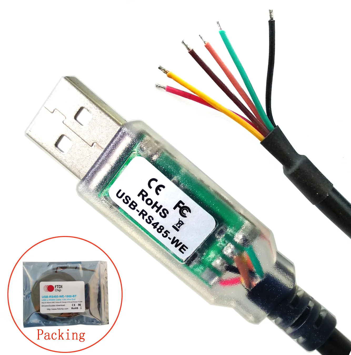
RJ45 Outlet
Section titled “RJ45 Outlet”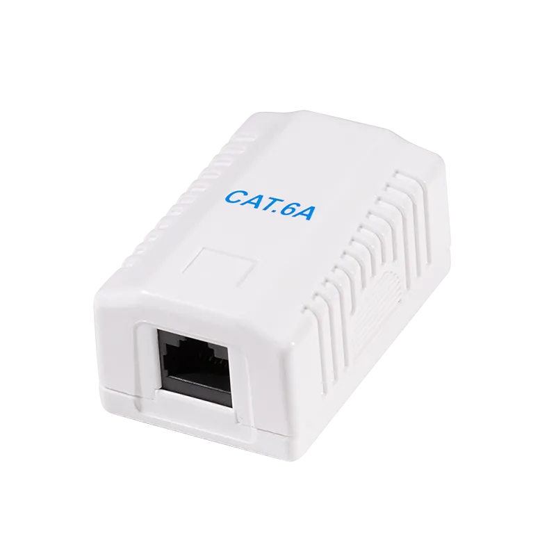
RJ45 Y-Connector
Section titled “RJ45 Y-Connector”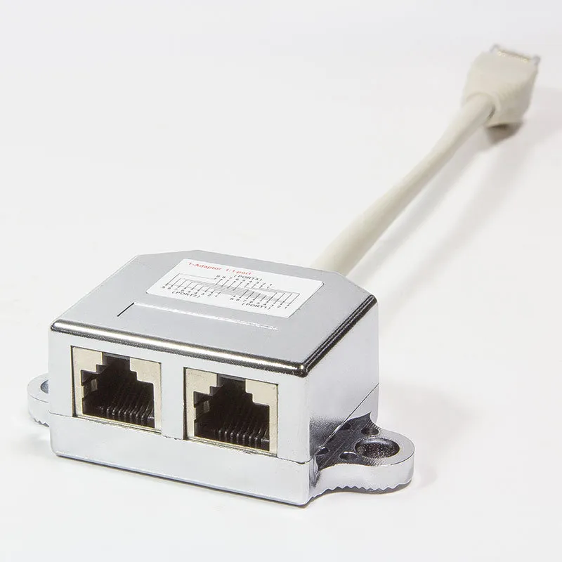
CAT5 Patch Cable
Section titled “CAT5 Patch Cable”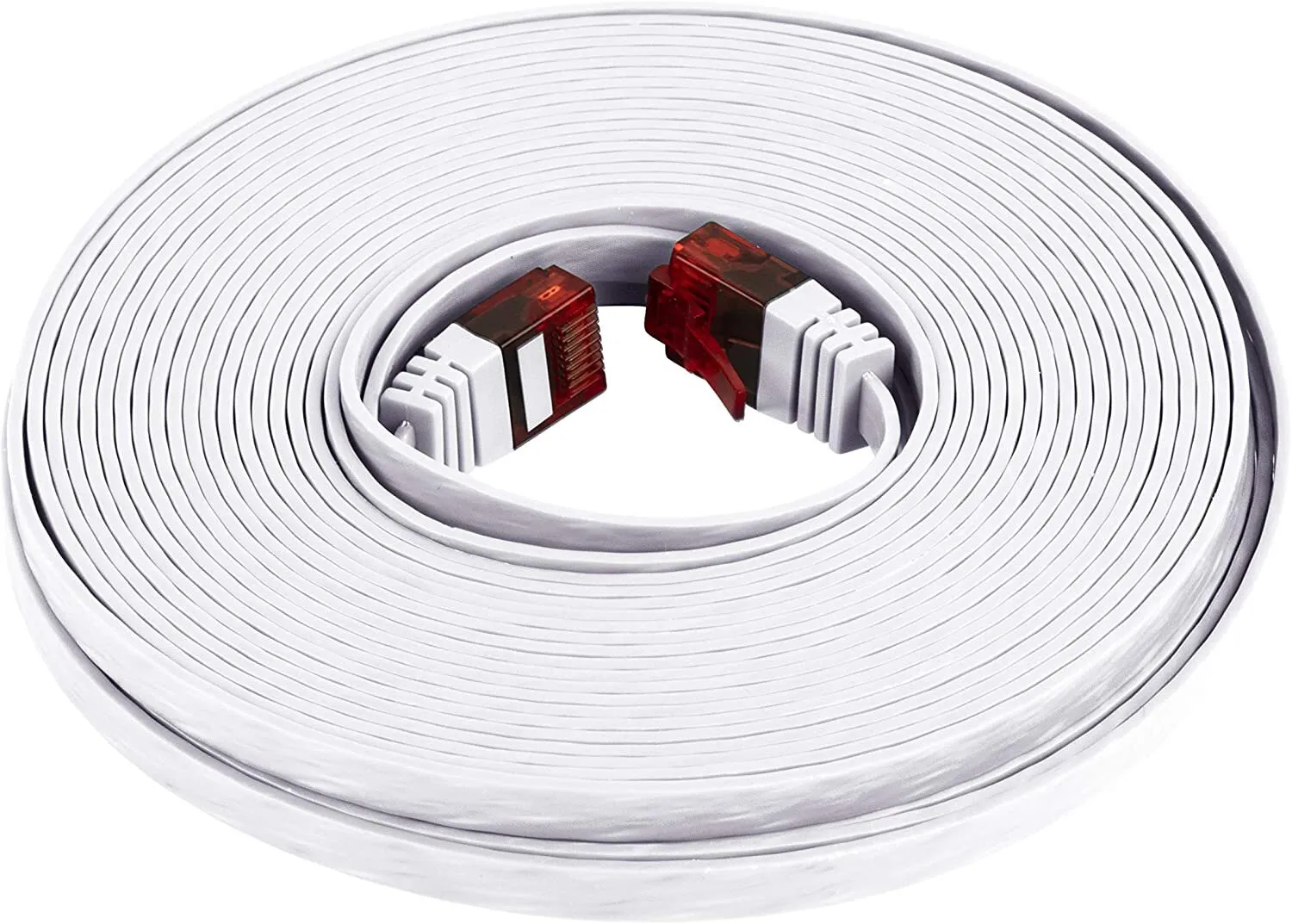
- Use a flat CAT5 patch cable between the RJ45 outlet and the first machine.
- Keep the cable run between 2 and 5 meters.
- Each next washing machine is connected through the RJ45 Y-connector of the previous machine.
- Maintain the bus chain order exactly as shown to avoid communication issues.
5. Maintenance
Section titled “5. Maintenance”Regular maintenance of the NT3200-32-MX Cashless Vending Machine is essential to ensure reliable operation, long service life, and high-quality user experience.
Maintenance tasks include periodic inspection of internal components, cleaning of external surfaces, and timely replacement of consumables such as receipt paper. All maintenance procedures must be performed with the device powered off unless explicitly stated otherwise.
5.1 Receipt Printer Paper Replacement
Section titled “5.1 Receipt Printer Paper Replacement”The device is equipped with an integrated thermal receipt printer that uses standard 80 mm thermal paper rolls. Thermal paper changes color when heated, enabling printing without ink.
Procedure
Section titled “Procedure”-
Open the printer compartment
- Unlock and open the front service door of the unit
- Locate the printer module and open the printer cover
-
Remove the used paper roll
- Take out the empty or remaining paper roll
- Remove any paper residues from the feed mechanism
-
Prepare a new paper roll
- Use only 80 mm thermal paper rolls
- Remove the outer adhesive layer of the roll
-
Insert the new paper roll
- Place the roll into the holder
- Ensure the paper feeds from the bottom towards the front (correct orientation is critical)
-
Feed the paper
- Pull out a short length of paper
- Align it with the paper guide and print head
-
Close the printer cover
- Close firmly until it clicks into place
-
Test the printer
- Power on the device
- Use the feed function or perform a test print
Important Notes
Section titled “Important Notes”- Incorrect paper orientation will result in no printing.
- Replace the roll when a colored indicator stripe appears on the paper.
- Do not use damaged or low-quality paper rolls.
- Avoid touching the thermal surface of the paper.
Proper paper installation ensures consistent print quality and prevents printer malfunctions.
6. Technical Data
Section titled “6. Technical Data”| Parameter | Value |
|---|---|
| Model | NT3200-32-MX |
| Enclosure | Metal kiosk |
| Display | 32″ capacitive touch screen |
| Mainboard | Intel-based |
| PSU | 220 V AC / 150 W |
| Frequency | 50–60 Hz |
| Phase | 1 / N / PE |
| Noise level | ≥ 50 dB |
| Operating temperature | 5 °C – 50 °C |
| Weight | 20–25 kg |
7. Contacts & Technical Service
Section titled “7. Contacts & Technical Service”| Manufacturer | maxcrc GmbH |
| Website | https://maxcrc.de |
For technical support, spare parts, or service requests, please contact maxcrc GmbH directly via the website above.