MX2150 Vending Unit - Technical Manual
Model: MX2150 Document version: v26.6.3 Manufacturer: maxcrc GmbH
1. Introduction
Section titled “1. Introduction”The MX2150 Vending Unit is a central control and payment system designed for self-service laundries. It provides a unified interface for managing washing machines, dryers, and detergent dispensing systems, ensuring efficient and automated operation of the entire laundry environment.
The unit is equipped with a 21,5-inch capacitive touch display, which serves as the primary user interface, allowing customers to easily select services, programs, and payment options.
The MX2150 supports a wide range of payment methods, including coins, banknotes, cashless payments (contact and contactless), RFID customer cards, and QR codes. The system is also capable of dispensing change, enabling full flexibility in customer transactions.
From an operational perspective, the vending unit allows administrators to configure individual pricing for each connected device, including different prices for specific washing or drying programs. Advanced pricing features such as Happy Hour tariffs, discounts for RFID card users, and promotional pricing strategies can be easily implemented to optimize business performance.
By combining hardware reliability with flexible software configuration, the MX2150 Vending Unit acts as a robust and scalable solution for modern laundromats.
This technical manual provides detailed information for installation, configuration, integration, and maintenance of the MX2150 unit within the Treysee vending ecosystem.
2. Safety and Usage
Section titled “2. Safety and Usage”This section provides important safety instructions and usage guidelines for the MX2150 Vending Machine. Following these recommendations ensures safe operation, prevents equipment damage, and prolongs device lifespan.
2.1 General Safety Instructions
Section titled “2.1 General Safety Instructions”- The device must be installed and operated only by qualified personnel.
- Always disconnect the power supply before performing any maintenance or service operations.
- Do not open the enclosure while the device is powered on.
- Ensure that the device is properly grounded.
- Do not use the device if visible damage to the housing, cables, or components is detected.
- Keep the device away from water, excessive humidity, and direct heat sources.
2.2 Electrical Safety
Section titled “2.2 Electrical Safety”- Use only the specified power supply and voltage parameters.
- Avoid overloading electrical circuits.
- Ensure stable power conditions; use surge protection if necessary.
- Do not operate the device with damaged power cables.
2.3 Operational Safety
Section titled “2.3 Operational Safety”- The device is designed for indoor use only.
- Do not block ventilation openings.
- Avoid exposure to dust, liquids, or aggressive chemicals.
- Do not place heavy objects on the device.
2.4 Usage Guidelines
Section titled “2.4 Usage Guidelines”- The NT2150 supports all types of payments.
- Users interact with the system via the touchscreen interface.
- Identification and access may be performed using:
- QR codes
- RFID cards
2.5 Maintenance and Service
Section titled “2.5 Maintenance and Service”- Regularly inspect the device for dust accumulation and clean it using dry, soft materials.
- Do not use liquid cleaners directly on the device.
- Service operations must be performed only by authorized personnel.
- Replace paper in the receipt printer according to manufacturer recommendations.
2.6 Misuse Prevention
Section titled “2.6 Misuse Prevention”- Do not attempt to modify or bypass system components.
- Do not use unauthorized peripherals or accessories.
- Any misuse may result in system malfunction and void warranty.
2.7 Emergency Situations
Section titled “2.7 Emergency Situations”In case of malfunction:
- Disconnect the device from power immediately.
- Do not attempt self-repair unless qualified.
- Contact technical support.
Proper adherence to these safety and usage guidelines ensures reliable and secure operation of the MX2150 device.
3. Product Description
Section titled “3. Product Description”The MX2150 manages payments and provides access control for laundry facility services, including:
- Washing and drying program selection and start
- Liquid and powder detergent dispensing
- QR-code and RFID gift card acceptance and validation
- Discount management
3.1 Components
Section titled “3.1 Components”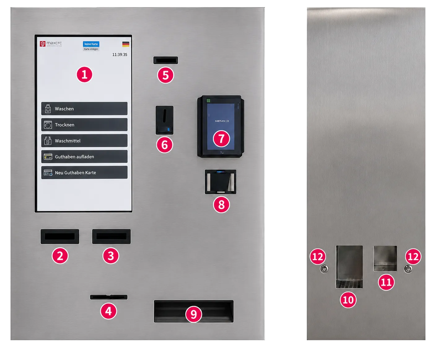
The device integrates the following components:
| No. | Component | Description |
|---|---|---|
| 1 | 21,5″ Capacitive Touch Display | Main user interface for selecting machines, programs, and payment options |
| 2 | Banknote Acceptor 1 | Accepts banknotes for payment; supported denominations are configurable in the backend system |
| 3 | Banknote Acceptor 2 | Accepts banknotes for payment; supported denominations are configurable in the backend system |
| 4 | Receipt Outlet | Slot for dispensing printed receipts; uncollected receipts can be automatically retracted into the device |
| 5 | Card Dispenser | Dispenses RFID or service cards to customers; also supports card reading and card intake |
| 6 | Coin Acceptor | Accepts coins for payment; includes a return button for rejecting and returning unaccepted coins |
| 7 | Card Terminal | Supports cashless payments (contact and contactless) |
| 8 | QR-Code, NFC Reader | Scanner for QR codes and barcodes (e.g. mobile payment or service access) |
| 9 | Change Dispenser | Dispenses coins as change after payment and returns coins not accepted by the system |
| 10 | Powder Detergent Dispenser Compartment | Compartment for dispensing powder detergent (can also be used for liquid detergent) |
| 11 | Liquid Detergent Dispenser Compartment | Compartment specifically designed for liquid detergent dispensing |
| 12 | Detergent Dispense Buttons (LED Indicator), 2 pcs | Buttons for dispensing detergent; LED status: red – dispensing in progress, green – ready for dispensing, press button |
3.2 Power Consumption
Section titled “3.2 Power Consumption”| Parameter | Value |
|---|---|
| Supply voltage | 220 V AC |
| Frequency | 50–60 Hz |
| Phase configuration | 1 / N / PE |
| Maximum power draw | 250 W |
3.3 Standards & Certifications
Section titled “3.3 Standards & Certifications”The MX2150 complies with the following standards:
- CE - European Conformity
- FCC - Federal Communications Commission (USA)
- RoHS - Restriction of Hazardous Substances
⚠️ WARNING
Incorrect installation may result in electric shock, fire, or equipment damage. This manual must be read in full before beginning installation. All electrical work must be performed by a qualified technician in accordance with local regulations.
3.4 Dimensions & Mounting Pattern
Section titled “3.4 Dimensions & Mounting Pattern”All dimensions are in millimetres. Refer to the drawing below.
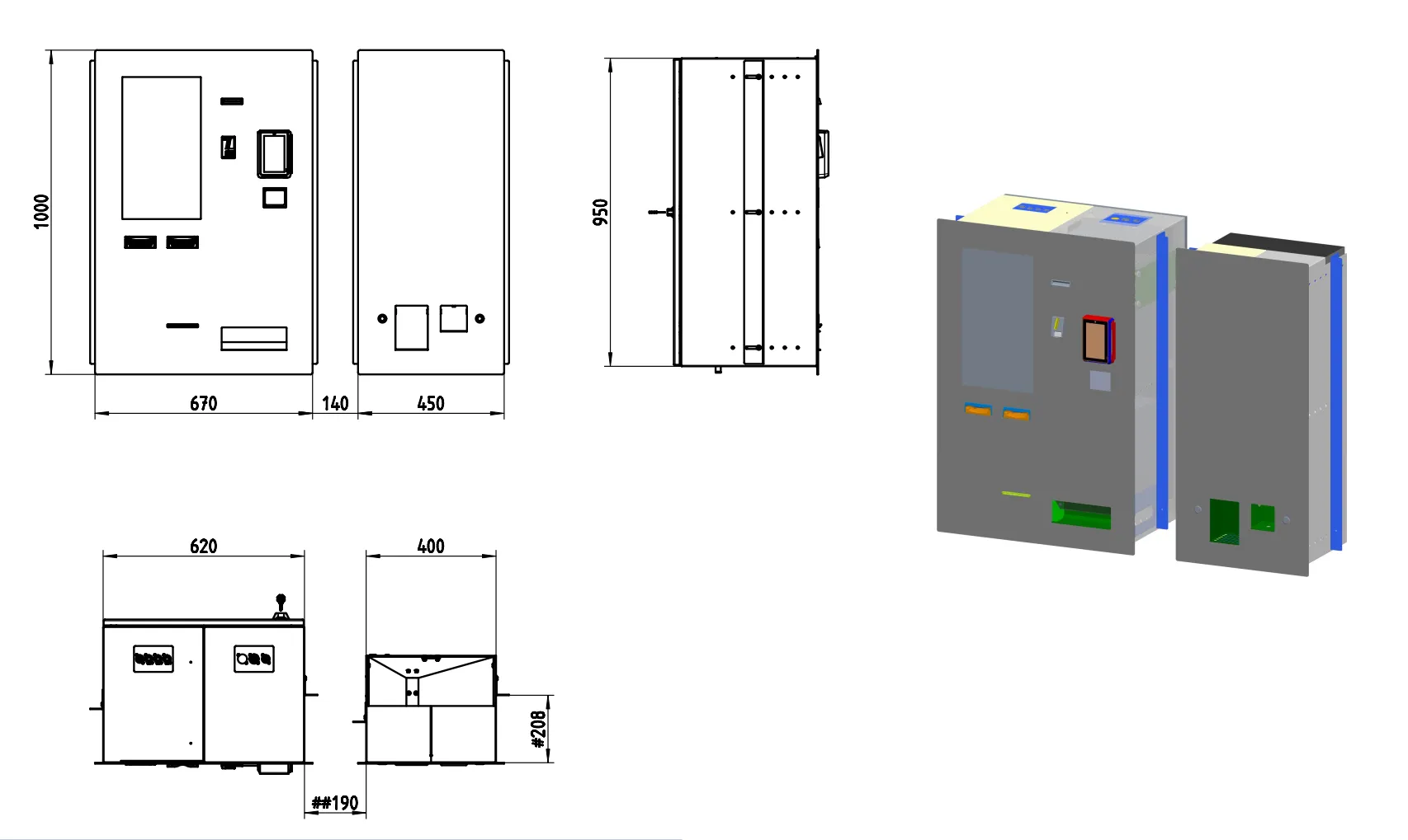
The MX2150 Vending Unit is designed for wall-mounted installation with an optional detergent dispenser module placed on the left or right side of the main control unit.
The installation requires two separate wall openings:
- Central Control Unit opening
- Detergent Dispenser opening
The minimum spacing between both wall openings must be ≥ 100 mm.
The recommended installation height for the lower edge of the wall opening is 750 mm from finished floor level.
The maximum permitted wall thickness is 125 mm.
For drywall constructions, an additional horizontal reinforcement below the wall opening is strongly recommended.
| Measurement | Value (mm) |
|---|---|
| Overall height | 1000 |
| Overall width (main unit) | 670 |
| Overall width (with detergent dispenser area) | 1260 |
| Overall depth | 400–450 |
| Front service projection | approx. 140 |
| Minimum wall cut-out – Central Unit | 630 × 960 |
| Minimum wall cut-out – Detergent Dispenser | 410 × 960 |
| Minimum spacing between openings | 100 |
| Recommended lower edge height from floor | 750 |
| Maximum wall thickness | 125 |
| Recommended cable duct height above openings | min. 50 |
| Minimum wall load capacity | 150 kg |
📐 see Picture 2 for the complete engineering drawing including front, rear, side, top, and mounting layout views.
4. Installation
Section titled “4. Installation”⚠️ Before starting: Ensure that mains power to the installation area is switched off at the breaker. Verify the wall structure can safely support a minimum load of 150 kg (device weight + installation safety margin).
The MX2150 is intended for professional wall-mounted installation in commercial laundry environments.
All washing machines, dryers, detergent dispensers, payment peripherals, and network infrastructure should be prepared before commissioning.
An active internet connection is mandatory for commissioning, remote diagnostics, monitoring, and service access.
4.1 Preparation Checklist
Section titled “4.1 Preparation Checklist”Before mounting the device, prepare and route the following cables to the installation point from behind the wall:
Power Supply
Section titled “Power Supply”- 230 V AC power cable
- Recommended cable type: NYM 3 × 1.5 mm²
- Connection: L / N / PE
- Protected according to local electrical regulations
Network Connection
Section titled “Network Connection”- Ethernet cable
- RJ45 connector required
- Routed from customer-provided internet router to the central control unit
Internet access is mandatory for commissioning.
Machine Communication
Section titled “Machine Communication”Cables to washing machines and dryers must be prepared according to the selected connection method:
Option A - Bus Connection (recommended)
Section titled “Option A - Bus Connection (recommended)”- One communication cable for washing machines
- One communication cable for dryers
- Each cable routed only to the first machine in the chain
Required cable type:
- EIB Y (St) Y 2x2x0.8
Communication type:
- RS485 (Modbus RTU)
Option B - Individual Relay Connection
Section titled “Option B - Individual Relay Connection”- One separate cable from the central unit to each washing machine / dryer
Ensure all cable lengths are sufficient before wall installation.
Additional Requirements
Section titled “Additional Requirements”- All washing machines and dryers must be electrically connected and fully operational
- A horizontal cable duct of minimum 50 mm above the wall openings is recommended
- Detergent dispenser supply lines should be routed through the same cable duct
Commissioning Preparation
Section titled “Commissioning Preparation”Prepare the following before first startup:
- Detergent and fabric softener for dispenser calibration
- Minimum hopper filling for change dispenser:
- 2 rolls of €2
- 2 rolls of €1
- 2 rolls of €0.50
- 2 rolls of €0.20
- 2 rolls of €0.10
- Active service contract with payment network provider (for example card4vend)
4.2 Mounting Steps
Section titled “4.2 Mounting Steps”Step 1 - Prepare Wall Openings
Section titled “Step 1 - Prepare Wall Openings”Create the required wall openings:
- Central Control Unit: 630 × 960 mm
- Detergent Dispenser: 410 × 960 mm
Maintain:
- Minimum spacing: 100 mm
- Maximum wall thickness: 125 mm
The detergent dispenser may be positioned either left or right of the main unit.
Step 2 - Mark Mounting Points
Section titled “Step 2 - Mark Mounting Points”Use the dimensional drawing and mounting template to mark all fixing points for the wall bracket and support structure.
Verify:
- Correct installation height (recommended 750 mm from floor)
- Proper alignment with detergent dispenser module
- Clearance for service access and front opening
Step 3 - Drill and Install Anchors
Section titled “Step 3 - Drill and Install Anchors”Drill the required anchor holes.
Use appropriate anchors depending on wall type:
- Concrete
- Brick
- Reinforced drywall with support structure
Install wall plugs and reinforcement where required.
For drywall installation, an additional horizontal support beam is strongly recommended.
Step 4 - Install Wall Bracket
Section titled “Step 4 - Install Wall Bracket”Secure the mounting bracket to the wall.
- Tighten all fixing points according to anchor manufacturer specifications
- Verify the bracket is perfectly level
Improper alignment may affect door operation and service access.
Step 5 - Route All Cables
Section titled “Step 5 - Route All Cables”Pull all prepared cables through the rear wall opening:
- Power supply
- Ethernet (RJ45)
- Machine communication cables
- Detergent dispenser connections
- Optional additional peripheral lines
Leave sufficient service length inside the unit.
Step 6 - Mount the Device
Section titled “Step 6 - Mount the Device”Carefully lift and position the MX2150 onto the mounting bracket.
Two installers are required.
Ensure:
- Stable seating on the bracket
- No cable pinching
- Correct positioning relative to detergent dispenser
Step 7 - Open Side Access Locks
Section titled “Step 7 - Open Side Access Locks”Use the supplied keys to unlock both service side locks.
Open the side access panels to access internal connection points.
Step 8 - Connect Internal Interfaces
Section titled “Step 8 - Connect Internal Interfaces”Connect:
- Power cable → Main Power Connector
- Ethernet cable → LAN Port
- Machine communication → RS485 / Relay IO Board
- Detergent dispenser → Internal dispenser control interface
- Card terminal / payment peripherals (if installed separately)
Verify all connectors are firmly seated.
Step 9 - Close and Lock the Unit
Section titled “Step 9 - Close and Lock the Unit”Close all service panels and lock both side access locks using the supplied keys.
Ensure all doors are securely closed.
Step 10 - Restore Power and Verify Startup
Section titled “Step 10 - Restore Power and Verify Startup”Switch mains power back on.
Check:
- Touchscreen starts correctly
- Printer initializes
- Coin and note acceptors respond
- Card terminal is online
- QR / NFC reader is detected
- Change dispenser initializes
- Detergent system responds
- Backend communication is active
Proceed with commissioning and software configuration.
4.3 Junction Box
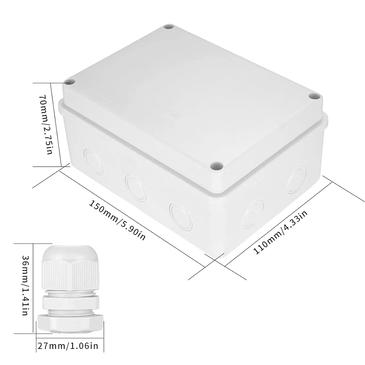
Section titled “4.3 Junction Box”The Junction Box is a surface-mounted protective enclosure designed to house the IO Board used for dryer machine control. The box provides IP65 protection against dust and moisture, making it suitable for installation in demanding service environments.
4.3.1 Purpose
Section titled “4.3.1 Purpose”The Junction Box is used to install the IO Board that controls 1 to 12 dryer machines, depending on the IO Board type and channel configuration.
4.3.2 Physical Data
Section titled “4.3.2 Physical Data”| Parameter | Value |
|---|---|
| Colour | White |
| Installation type | Surface-mounted |
| Protection class | IP65 |
| Dimensions (D × W × H) | 7 cm × 11 cm × 15 cm |
- Mount the IO Board inside the Junction Box before final wall installation.
- Keep cable entries sealed to preserve the IP65 rating.
- Use the Junction Box when the IO Board is deployed for dryer machine control in wet or dusty areas.
4.3.3 Wiring Diagram
Section titled “4.3.3 Wiring Diagram”The diagram illustrates the connection of the cashless vending unit to the Modbus IO board and multiple dryers, including power supply, communication lines, and relay control signals.
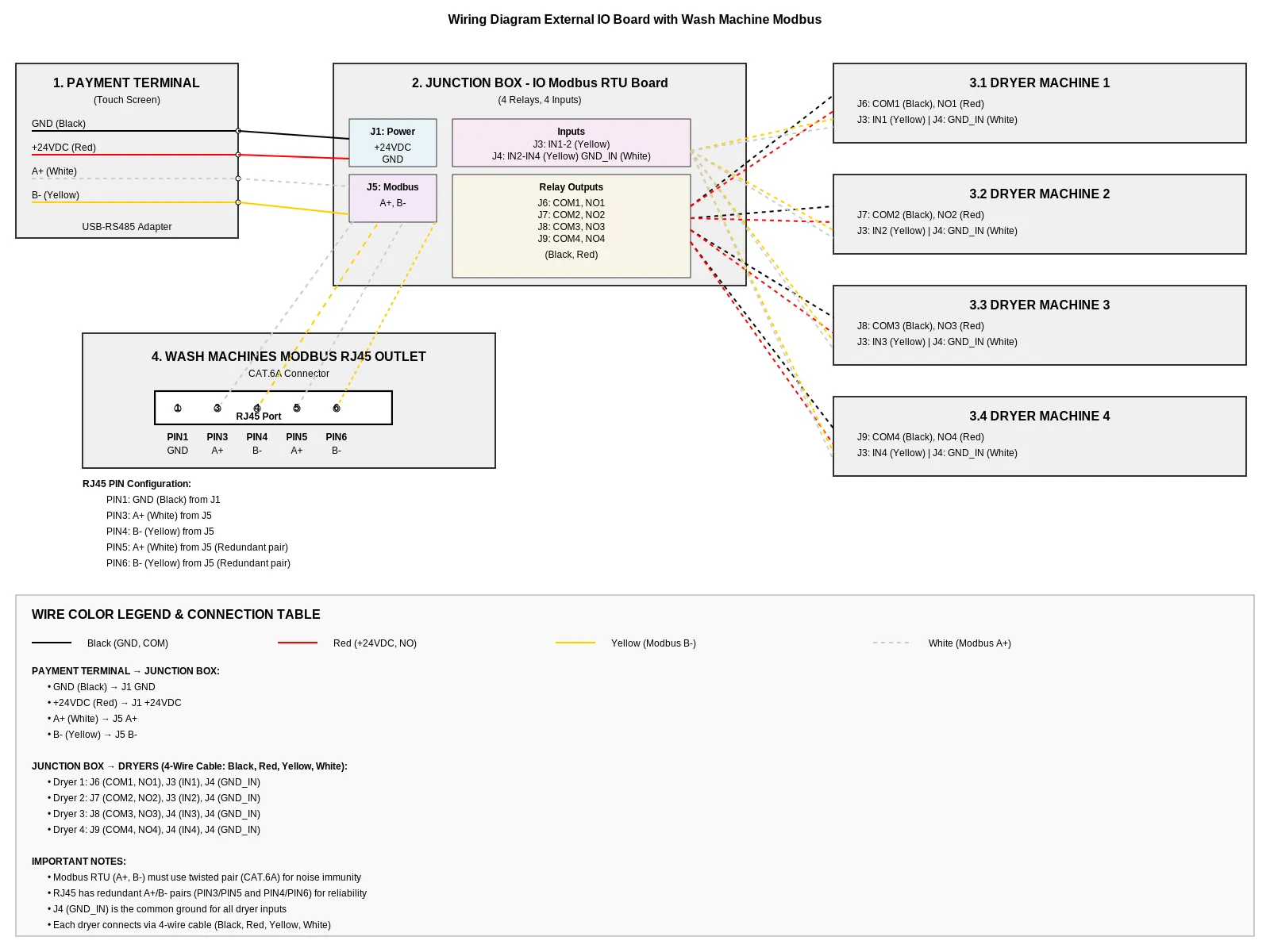
4.3.4 Vending Machine, IO Board, and Dryers
Section titled “4.3.4 Vending Machine, IO Board, and Dryers”The Vending Unit (VU) provides power and RS485 communication to the IO Board. The IO Board then distributes relay start signals and feedback inputs to one to four dryer machines.
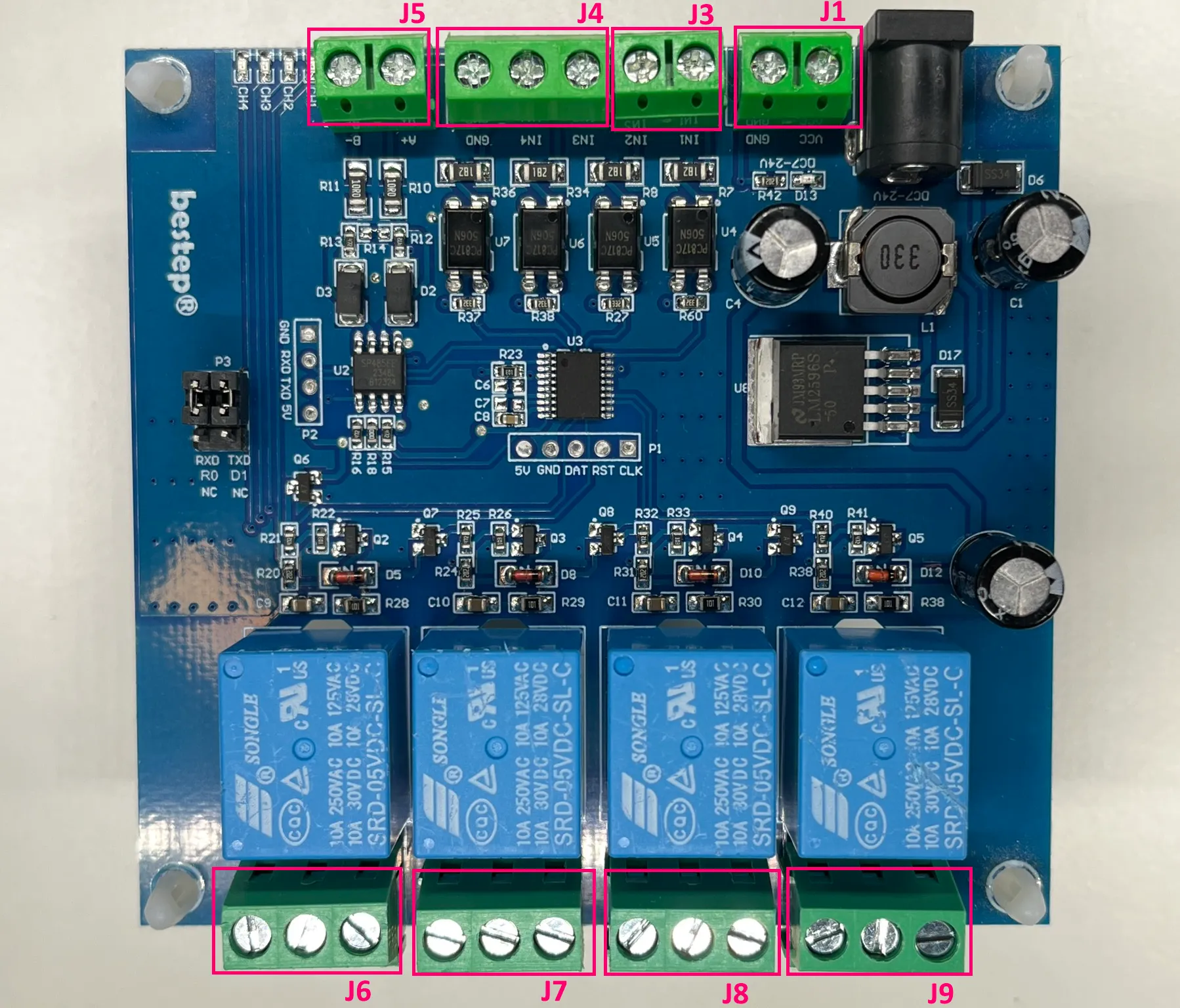
VU to IO Board
Section titled “VU to IO Board”| VU Wire | Color | IO Board Terminal | Signal |
|---|---|---|---|
| +12/24 VDC | Red | J1 | Power supply |
| GND | Black | J1 | Power ground |
| RS485 A+ | Yellow | J5 | RS485 A+ |
| RS485 B- | White | J5 | RS485 B- |
IO Board to Dryer 1
Section titled “IO Board to Dryer 1”| IO Board Terminal | Wire Color | Dryer Connection | Signal |
|---|---|---|---|
| J6 / NO1 | Red | Start input | Relay start pulse |
| J6 / COM1 | Black | Common | Relay common |
| J3 / IN1 | Yellow | Busy feedback | Dryer busy signal |
| J4 / GND_IN | White | Feedback ground | Feedback reference |
IO Board to Dryer 2
Section titled “IO Board to Dryer 2”| IO Board Terminal | Wire Color | Dryer Connection | Signal |
|---|---|---|---|
| J7 / NO2 | Red | Start input | Relay start pulse |
| J7 / COM2 | Black | Common | Relay common |
| J3 / IN2 | Yellow | Busy feedback | Dryer busy signal |
| J4 / GND_IN | White | Feedback ground | Feedback reference |
IO Board to Dryer 3
Section titled “IO Board to Dryer 3”| IO Board Terminal | Wire Color | Dryer Connection | Signal |
|---|---|---|---|
| J8 / NO3 | Red | Start input | Relay start pulse |
| J8 / COM3 | Black | Common | Relay common |
| J4 / IN3 | Yellow | Busy feedback | Dryer busy signal |
| J4 / GND_IN | White | Feedback ground | Feedback reference |
IO Board to Dryer 4
Section titled “IO Board to Dryer 4”| IO Board Terminal | Wire Color | Dryer Connection | Signal |
|---|---|---|---|
| J9 / NO4 | Red | Start input | Relay start pulse |
| J9 / COM4 | Black | Common | Relay common |
| J4 / IN4 | Yellow | Busy feedback | Dryer busy signal |
| J4 / GND_IN | White | Feedback ground | Feedback reference |
- Red and black wires carry the start pulse from the relay.
- Yellow and white wires carry the busy feedback from the dryer.
- The “busy” signal from the Dryer is a positive voltage pulse ranging from +12 VDC to +24 VDC between GND_IN and the corresponding IN1–IN4.
- One IO Board supports up to four dryer machines when wired according to the available relay and input channels.
- Keep cable runs short.
4.3.5 Wash Machines RS485 Bus
Section titled “4.3.5 Wash Machines RS485 Bus”The Wash Machines RS485 Bus connects the Vending Machine to the washing machines through an external RS485 adapter and RJ45 cabling.
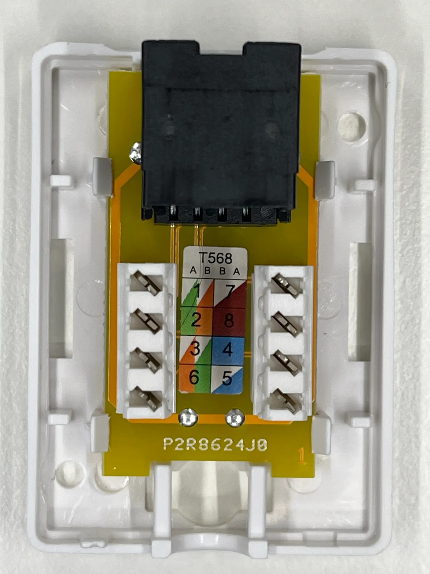
Laundry Machine Connection Socket (RJ45 / Modbus)
Section titled “Laundry Machine Connection Socket (RJ45 / Modbus)”This socket is a communication interface used to connect washing machines and dryers to the central control system (Vending Unit) via Modbus RTU using an RJ45 connector.
The socket is based on a standard module with terminal blocks and T568A/B color coding, simplifying connection of twisted pair cables (CAT5/CAT6).
Key Features
Section titled “Key Features”- Connection type: RJ45 (8P8C)
- Interface: RS485 (Modbus RTU)
- Wiring standards supported: T568A / T568B
- Wire termination: spring terminals (tool-less or tool-assisted)
- Purpose: data communication and control signal transmission between vending unit and machines
Pin Assignment
Section titled “Pin Assignment”- PIN1 GND - ground (Black) from J1
- PIN3 - A+ (White) from J5
- PIN4 - B- (Yellow) from J5
- PIN5 - A+ (White) from J5 (Redundant pair)
- PIN6 - B- (Yellow) from J5 (Redundant pair)
Application
Section titled “Application”Used for connecting:
- washing machines
- dryers
- detergent dispensing systems
to the central vending/control unit
Connection Order
Section titled “Connection Order”- Vending Machine → USB-RS485-WE Adapter
- USB-RS485-WE Adapter → RJ45 outlet
- RJ45 outlet → flat CAT5 patch cable
- Cable length: 2 to 5 meters
- Flat CAT5 patch cable → RJ45 Y-connector of the first washing machine
- First washing machine Y-connector → next washing machine Y-connector
- Continue the chain from one RJ45 Y-connector to the next until all washing machines are connected.

USB-RS485-WE Adapter
Section titled “USB-RS485-WE Adapter”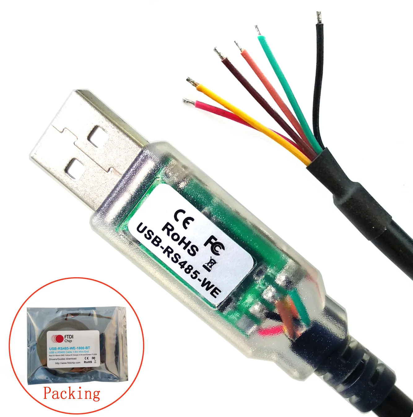
RJ45 Outlet
Section titled “RJ45 Outlet”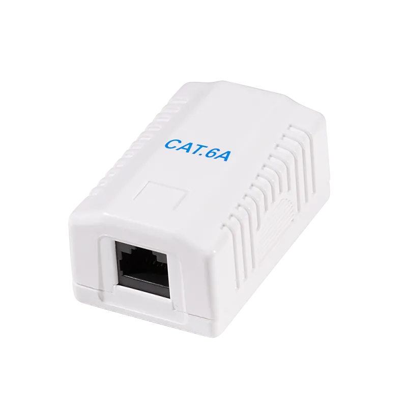
RJ45 Y-Connector
Section titled “RJ45 Y-Connector”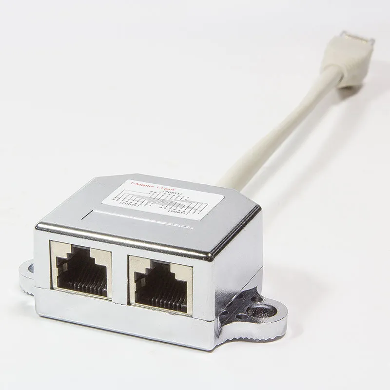
CAT5 Patch Cable
Section titled “CAT5 Patch Cable”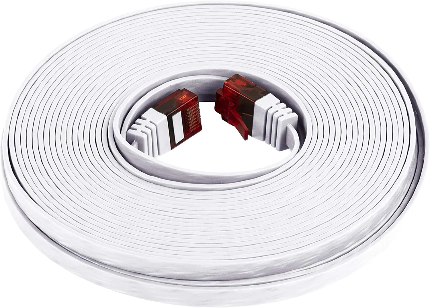
- Use a flat CAT5 patch cable between the RJ45 outlet and the first machine.
- Keep the cable run between 2 and 5 meters.
- Each next washing machine is connected through the RJ45 Y-connector of the previous machine.
- Maintain the bus chain order exactly as shown to avoid communication issues.
5. Maintenance
Section titled “5. Maintenance”Regular maintenance of the MX2150 Vending Machine is essential to ensure reliable operation, long service life, and high-quality user experience.
Maintenance tasks include periodic inspection of internal components, cleaning of external surfaces, and timely replacement of consumables such as receipt paper. All maintenance procedures must be performed with the device powered off unless explicitly stated otherwise.
5.1 Receipt Printer Paper Replacement
Section titled “5.1 Receipt Printer Paper Replacement”The device is equipped with an integrated thermal receipt printer that uses standard 80 mm thermal paper rolls. Thermal paper changes color when heated, enabling printing without ink.
Procedure
Section titled “Procedure”-
Open the printer compartment
- Unlock and open the front service door of the unit
- Locate the printer module and open the printer cover
-
Remove the used paper roll
- Take out the empty or remaining paper roll
- Remove any paper residues from the feed mechanism
-
Prepare a new paper roll
- Use only 80 mm thermal paper rolls
- Remove the outer adhesive layer of the roll
-
Insert the new paper roll
- Place the roll into the holder
- Ensure the paper feeds from the bottom towards the front (correct orientation is critical)
-
Feed the paper
- Pull out a short length of paper
- Align it with the paper guide and print head
-
Close the printer cover
- Close firmly until it clicks into place
-
Test the printer
- Power on the device
- Use the feed function or perform a test print
Important Notes
Section titled “Important Notes”- Incorrect paper orientation will result in no printing.
- Replace the roll when a colored indicator stripe appears on the paper.
- Do not use damaged or low-quality paper rolls.
- Avoid touching the thermal surface of the paper.
Proper paper installation ensures consistent print quality and prevents printer malfunctions.
6. Technical Data
Section titled “6. Technical Data”| Parameter | Value |
|---|---|
| Model | MX2150 |
| Enclosure | Metal kiosk |
| Display | 21,5″ capacitive touch screen |
| Mainboard | Intel-based |
| PSU | 220 V AC / 250 W |
| Frequency | 50–60 Hz |
| Phase | 1 / N / PE |
| Noise level | ≥ 50 dB |
| Operating temperature | 5 °C – 50 °C |
| Weight | 135 kg |
7. Contacts & Technical Service
Section titled “7. Contacts & Technical Service”| Manufacturer | maxcrc GmbH |
| Website | https://maxcrc.de |
For technical support, spare parts, or service requests, please contact maxcrc GmbH directly via the website above.